A Guide- Understanding the First Angle Projection vs. Third Angle Projection in Engineering Drawings

Understanding the First Angle Projection vs.Third Angle Projection in Engineering Drawings is necessary AS Multi-view orthographic projection is the primary means of graphic communication utilized in engineering.
Engineering Drawings comprise of how and how items are made.Using orthographic projection all techniques are build.
Multi-view is a technique that uses 2 or more projections of an object in an orthographic projection to convey the shape and dimensions of the object, so that the shop or job site has all the information necessary to create it.
To create a 2D view of a three-dimensional object, orthographic projection is used. These are created by drawing parallel lines to show the views of an object onto a flat surface.
What is an Orthographic Projection?
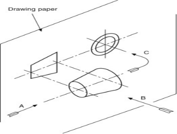
In orthographic projections, every different angle of an object is projected onto a plane, as if someone was looking at the object from the other side.
The included reference planes are:
- Horizontal Plane (HP)
- Vertical Plane (VP)
- Side or Profile Plane (PP)
The included view point are:
- Top View (TV) – Projected on HP
- Front View (FV) – Projected on VP
- Side View (SV) – Projected on PP

Orthographic projection technique can create two types of drawings:
- Multi-view drawings where each view depicts an item in two dimensions
- All three dimensions are displayed in a single view in axonometric drawings
When a three-dimensional object is on a plane, it’s only shown adequately in a two-dimensional image. Either not enough of the object can be seen or certain parts are distorted. For the most accurate representation, another method has to be used.
Projection can be seen by observing shadows cast onto a two-dimensional surface, proving that the object is projected there.
Lines are projected onto a surface to depict 3D objects objects using the orthographic projection system.
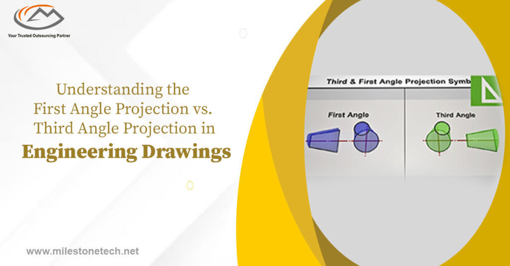
First Angle Projection vs. Third Angle Projection
Understanding the First Angle Projection vs. Third Angle Projection in Engineering Drawings is-
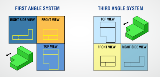
Orthographic views: The traditional three different orthographic perspectives are noticeable in both first point and third point projection of a given part or get together. The primary distinction between the first angle and third angle method is the design of the component on the sheet.

What is a First Angle Projection In Engineering Drawings?
Orthographic projection is the most popular way to acquire engineering drawings. It has three views front,edge and top. The vertical plane at right angles to the viewer is also a fundamental element in this technique, as it is in angle projection, which is accepted everywhere but the US and Japan. Views are created by positioning your object so it appears above the horizontal plane and aligns with the vertical plane.

Attributes of First Angle Projections in Engineering Drawings:
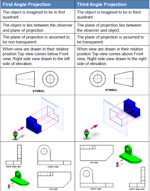
- Positioning of the the object is in the first quadrant
- They are mostly used in countries like India, Canada & Europe
- The Projection plane is opaque
- The front perspective is represented by top of the axis
- The object is positioned directly between the two in First Angle Projection, and not in Third Angle Projection
What is the Third Angle Project in Engineering Drawings?
3D objects are realistically shown in 3D on a 2D screen with the perspective projection technique. The US primarily uses third angle projection for its industrial designs, which require transparency to create the most realistic effect. Thus in the third angle projection the projection planes are transparent
The Following are the Characteristics of Third Angle Projection in Engineering Drawings
- These are typically US and Australia
- The object is placed at one end projection plane in the middle and the observer at the end
- Positioning of the object is in the third quadrant
- The front perspective is represented by the bottom of the horizontal axis
- The left side of the vertical axis has left view
The language of graphics or drawings has a greater importance to designer, technician, sanitarian and engineer which used to communicate designs to others. It is written in the form of shape, size and specifications of physical bodies.
Follow Milestone PLM Solutions for Mechanical Industry Updates, CAD Tips and Global CAD, CAM & FEA News.
Milestone PLM Solutions with its exclusive delivery center in India is a global CAD, CAM & FEA services outsourcing partner serving the needs of the Mechanical, Millwork and Automotive industry since 2004. MILESTONE focuses on the unique needs of clients and believe in tackling real-life problems with efficiency, smooth and ease.
The MILESTONE team can assist you with Product Design, 3d Modeling, Drafting & detailing, Reverse Engineering, FEA Analysis and more. We support multiple software including AutoCAD, Solidworks, Catia, NX, Inventor, Solidedge & Ansys etc. Our approach is to provide a dedicated team for each customer over ongoing project and deliver the quality output consistently.
With our state of art technology and large talent pool of Engineers, we are developing best in class solutions for our customers across the globe. We align with your culture and values to form unbreakable partnerships and are primed for success with over 100 employees and 150 customers in the US, Europe, India, and Asia.
For more queries regarding any of the above-mentioned topics, feel free to connect with us on our website www.milestonetech.net or contact us on +1-844-598-0005
